

Noise, Timing, and the Network Interface in High-Resolution Audio Systems
The Short Version
Skip to the full article →
Confirmation was not necessary, but it’s nice to know that I am but one thread in the Great Tapestry that is life itself. While I was aware of the impending annual tech issue of The Absolute Sound (Issue 373), I was not privy to its contents when I set out to create this article.
Much of the information herein surfaced in Robert Harley’s interview with Reiki Audio Limited’s Founder and Designer, Nigel Bell. Here, though, we take a deeper empirical dive than the limitations of print would allow.
It is easy for audiophiles to view home networks used for streaming and music distribution as generic. They are not, so this article addresses the many decisions audiophiles implicitly or explicitly make in building and managing music distribution systems for audio.
A caveat: this is a long and fairly technical article, and the short summary below cannot capture the full reasoning behind it. It is meant only to give you the shape of the argument and where it lands. The details—why each type of connection behaves the way it does, along with the equations and trade-offs that support the claims—live in the full text, so this summary is necessarily incomplete on its own.
In a high-resolution audio system, the way the network signal physically enters the streamer or DAC can shape the sound—not because data is lost (the bits arrive intact), but because the interface hardware injects high-frequency electrical noise and timing error into the sensitive analog and clock circuits just past the network boundary. This paper models that effect with two linked equations—one for net structural noise (N_net), one for total timing jitter (J_total)—and uses them to weigh the three physical connections an audiophile can actually choose between.
The discussion here assumes that you understand and accept that noise-based and computational timing errors can affect sound quality in digital audio systems. At a basic level, confusion around this is due to a distinction between digital audio and digital computing. In most digital computing consumers are accustomed to, numbers matter and timing does not. In audio for music, the timing of digital data is fundamental to the signal recovered for ultimate analog playback. How the latter can go wrong is a long subject, but we want to acknowledge this premise.
There is no universal winner. Passively isolated copper cables (standard Ethernet cables with RJ45 terminations) block upstream noise with magnetic transformers but pay for it in local processing hash, because their interface chips run heavy real-time equalization; their timing budgets are dominated by that noise-induced modulation. Optical fiber severs the electrical path entirely, driving upstream noise effectively to zero—but the active transceiver module adds its own noise floor and, more importantly, a clock-recovery penalty that becomes its largest source of jitter. The SFP direct-attach copper (DAC) hybrid keeps both terms low and models as the quietest of the three, at the cost of a shared DC ground path that has to be kept clean. Each architecture trades electrical noise against timing integrity in a different place, so the best choice depends on the system around it. Rather than worrying about which approach to use, it may be best to review what you are using and make sure the entire signal path attends to a good approach all along the chain from modem to DAC.
Two caveats frame everything that follows. First, the numbers used throughout are illustrative engineering estimates, not laboratory measurements, and the audible consequences are reported by listeners rather than proven by controlled testing—the framework describes a plausible mechanism, not a settled result. Second, the purity of the master clock itself (J_intrinsic) does not depend on which cable you choose, which is why it is treated as a separate matter at the end.
On This Page
- Introduction: The Physical Layer of the Digital Stream
- Technical Primer: The Language of the Wire
- The Core Mathematical Framework
- Player 1: Passively Isolated Copper (RJ45)
- Player 2: Audio-Optimized SFP / Optical (Fiber)
- Player 3: The Low-Overhead Hybrid (SFP DAC Twinax)
- Architectural Synthesis: The Nonpartisan Matrix
- The Frontier of Future Innovation
- Where to Begin: Prioritizing the Chain from Modem to DAC
- Additional Consideration: The Clocking Hierarchy
Introduction: The Physical Layer of the Digital Stream
The transition from physical media to network streaming brought with it a comforting engineering shorthand: “bits are bits.” Digital audio travels the local network as discrete binary packets governed by robust error-correction protocols, so—the assumption goes—the physical medium has no bearing on the final acoustic result. If the checksums match and the data arrives intact, the mathematical representation of the music remains perfect.
This overlooks the reality that digital networking is an analog, physical process: packets propagate as high-frequency voltage shifts or optical pulses over physical media bound by the laws of electrodynamics.
In a high-resolution playback system, the operational hurdle is not data delivery—TCP transport, which carries most local network audio protocols, guarantees that every packet ultimately arrives intact. The challenge is signal integrity: how the network’s physical execution impacts the local electrical and timing environment of the digital-to-analog converter (the system’s DAC).
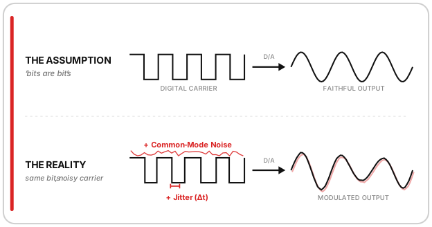
When high-frequency electrical noise or timing variations cross the hardware boundary into an audio component, they do not alter the binary code of the music file—a .flac or .wav file remains bit-perfect. Instead, this parasitic energy enters via common-mode leakage, ground loops, or localized transceiver processing overhead, and interacts with the component’s internal power rails and ground planes.
This interaction causes minute voltage fluctuations that directly modulate the master clock generator, translating physical anomalies at the network layer into phase noise, or jitter, during digital-to-analog reconstruction. Psychoacoustically, the failure mode listeners describe is never a dropout or an audible glitch—it’s subtler: a perceived loss of soundstage depth, a softening of image focus, and a slight flattening of natural timbral textures.
To address these vulnerabilities, the high-end audio industry has split into competing design philosophies, each prioritizing different engineering vectors to manage noise and timing—fueling years of partisan debate among hobbyists and manufacturers alike.
Rather than defending a single approach, this analysis evaluates three independent topologies, each in a highly optimized configuration: traditional copper RJ45 conductors, SFP/Optical fiber paths, and SFP Direct Attach Copper (DAC) hybrid cables. Understanding the physics and structural trade-offs of all three lets us move past tribal biases and examine how each format addresses the core challenges of high-fidelity network playback.
Technical Primer: The Language of the Wire
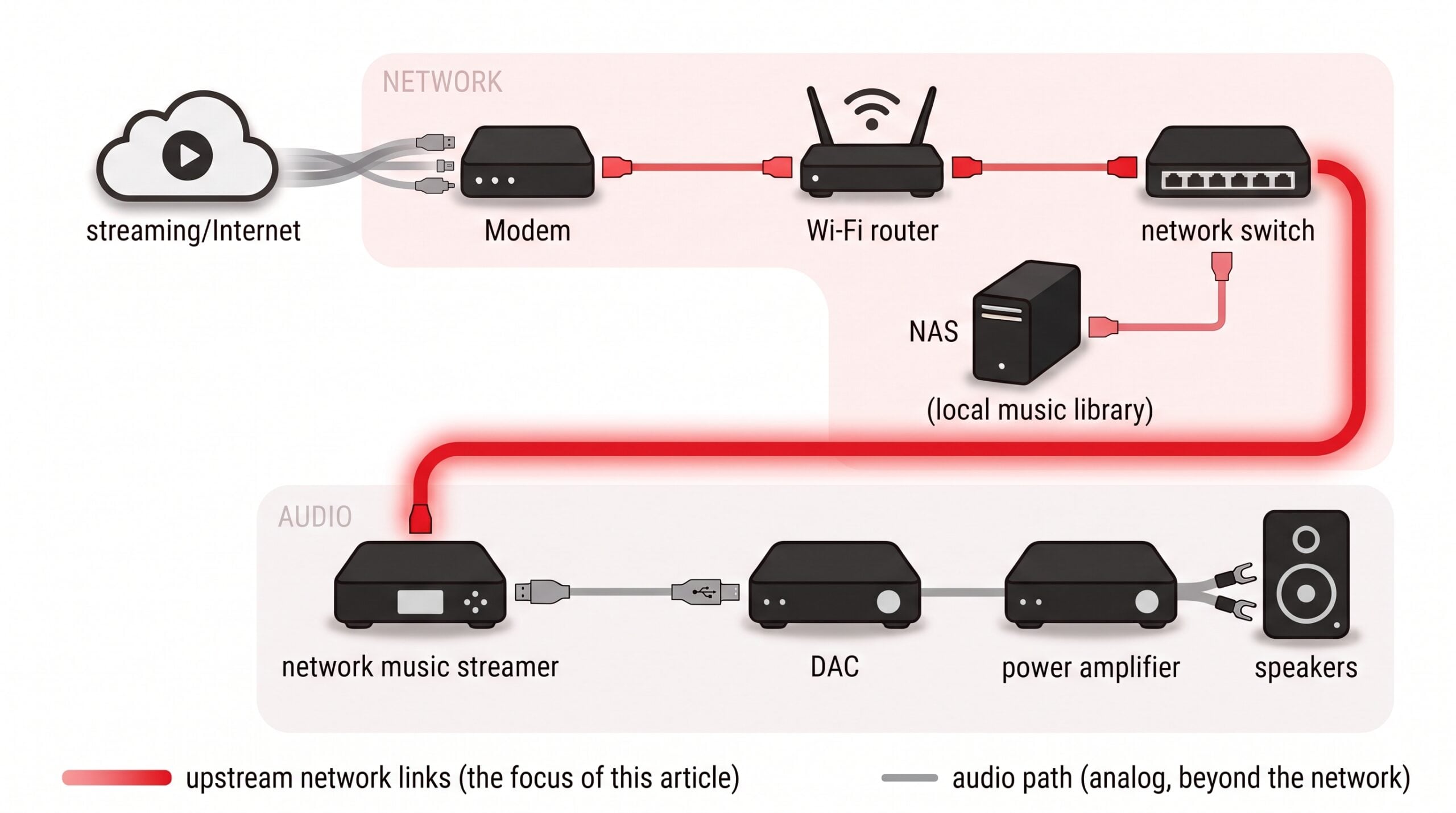
To evaluate how a network interface interacts with a high-resolution playback chain, we need a shared vocabulary grounded in physical-layer mechanics. Streaming data enters an audio component as a physical phenomenon that must cross a defined hardware boundary.
Physical Layer (PHY) circuitry: Integrated right at the entrance of the chassis, the PHY microchip defines the electrical or optical signaling parameters of the device, dictating how raw incoming pulses are translated into established network communication.
Connection interfaces: RJ45 is ubiquitous in traditional network layouts, this physical interface is implemented via a native copper port, passing electrical data over twisted-pair conductors. Alternatively, hardware designers can deploy the Small Form-factor Pluggable (SFP) architecture. The SFP interface consists of a hot-swappable metal cage that acts as a standardized mechanical dock. The cage itself contains no active electronics, but its internal edge connector delivers 3.3-volt power from the host device to whatever module is plugged in. Depending on the design goals of the system, this single SFP cage can accept either an active optical transceiver module to run fiber lines, or a passive Direct Attach Copper twinaxial cable.
Here the audiophile must navigate a confusing collision of terminology: networking universally abbreviates this passive, high-bandwidth interconnect as a DAC cable. It must not be confused with the system’s downstream DAC (the Digital-to-Analog Converter) responsible for rendering the music; context will remain our anchor.
Serializer/Deserializer (SERDES): Whichever medium a system selects, the high-speed data stream must interface with the component’s internal processing buses. Network data moves along the cable as a rapid serial stream while those internal buses are parallel; the SERDES is the translator between the two. It converts the processor’s wide parallel data paths into a single high-speed serial stream for transmission, and unpacks it identically back into parallel data at the destination.
Modal Dispersion and Return Loss: As these serialized signals propagate across physical media, they encounter specific mechanical and geometric boundaries that can deform the waveform. In optical networks, an improper selection of fiber core dimensions can introduce temporal distortion where light rays scatter along multiple reflective paths inside a wide core, causing the optical pulse to broaden and blur over distance. At any junction where copper pins mate or fiber lines connect, the transmission faces a degradation known as Return Loss. This measures the signal energy reflected back toward the source by microscopic air gaps, misalignments, or physical discontinuities. The resulting echo can destabilize the driving clock or laser source.
Galvanic Isolation: To keep external common-mode noise out of the sensitive internal processing zone, engineers evaluate the system’s capacity for galvanic isolation. This methodology completely separates conductive circuits—blocking DC offsets and stray noise currents—while still permitting data transfer through light or magnetic fields.
Jitter: Ultimately, any network topology is judged by its ability to minimize jitter. Jitter—phase noise, viewed in the time domain—is the microscopic deviation of a signal’s pulse timing relative to an ideal reference clock. In the digital-to-analog reconstruction phase, this timing instability modulates the conversion clock, which could turn hidden physical anomalies at the network layer into audible changes in soundstage focus, transient definition, and timbral purity.
The Core Mathematical Framework
To move from subjective impressions to rigorous analysis, we model the network interface as an electronic system, using two interlocking frameworks—one governing high-frequency electrical noise, the other timing integrity—as an objective baseline for comparing our three configurations.
The first vector of our framework governs the transmission of high-frequency electrical noise across the network boundary layer. This behavior can be systematically mapped using the Net Algebraic Noise Equation of a hardware interface:

In this linear model, N_upstream represents the total common-mode electromagnetic noise injected into the network path by upstream consumer electronics, residential appliances, and the power grid. The variable A_medium is the attenuation coefficient, or isolation efficiency, inherent to the selected physical communication medium, representing a multiplier between 1 (complete transmission—no attenuation) and 0 (complete blocking of upstream noise), which can also be expressed on a logarithmic decibel scale, where 0 dB denotes full transmission and increasingly negative values denote stronger isolation. Finally, N_local represents the self-generated high-frequency electrical noise and circuit hash introduced directly by the receiving component’s local interface hardware.
To ground the equation, we’ll define a control environment: an average modern household network, in which switching power supplies and high-speed processors continuously dump common-mode noise onto local data lines across the 1 MHz to 250 MHz radio band. This baseline pollution is normalized as our control starting point: N_upstream = 0 dB.
The second vector of our framework addresses timing integrity, mapping how this physical network noise converts into timing errors at the digital-to-analog conversion boundary. Because network data packets do not carry a real-time audio clock, network noise degrades playback via indirect clock modulation. When high-frequency electrical noise (N_net) penetrates the chassis, it leaks into internal ground planes and local DC power rails, dynamically shifting the threshold switching voltages of local crystal oscillators.
This interaction can be modeled through the formula for Total System Phase Jitter (J_total) at the conversion layer:

Here, J_intrinsic represents the native phase noise of the master oscillator crystal itself. J_modulated represents the jitter induced by electrical noise infiltrating the local circuit environment—directly proportional to N_net and influenced by processor load spikes during hardware interrupts. J_translation represents the additive phase noise introduced by the serialization, deserialization, and clock-recovery loops required by certain connection types. Because these three components are largely uncorrelated random processes, they combine as the root-sum-of-squares (RSS) shown above rather than a simple arithmetic total; a plain linear sum of the three would instead represent a conservative worst-case bound on total timing error.
By evaluating our three network topologies against these two interlocking equations under our normalized household baseline, we can observe precisely how the engineering trade-offs shift from one approach to the next.
Player 1: Passively Isolated Copper (RJ45)
The audio-centric copper architecture is rooted in timing simplicity and power-rail stability. Proponents such as Silent Angel, with their flagship Bonn NX infrastructure, argue that the most elegant way to preserve signal integrity is to avoid the format conversions and active serialization inherent to optical networking—maintaining an unbroken, purely electrical signaling path that capitalizes on native network timing.
The primary engineering advantage of a native copper architecture is that its physical-layer chip runs directly on the standard 25 MHz Gigabit Ethernet reference clock, with no optical conversion stage in the signal path. (Strictly speaking, 1000Base-T links are loop-timed—one PHY acts as timing master while its link partner recovers receive timing from the incoming signal—so the advantage lies in the local clocking architecture rather than in any shared clock line. Note also that this 25 MHz figure clocks the network interface, not the DAC itself: the DAC runs in its own timing domain, from its own local audio-frequency master oscillators, and is outside the scope of this discussion.) Data arriving over an unbroken twisted-pair line maps directly to the system’s native Ethernet controllers, allowing engineers to tie the physical layer straight into an ultra-low-phase-noise internal master clock—such as a Temperature-Compensated (TCXO) or Oven-Controlled (OCXO) Crystal Oscillator—without intermediate rate-matching translation layers.
Furthermore, by eliminating active optical conversion modules, the network interface operates under a highly predictable, static power envelope. Linear power supplies with multi-stage regulation can be optimized for a completely rigid electrical load, achieving exceptionally low voltage ripple because the circuit never demands sudden, dynamic current spikes to drive laser elements.
Copper’s continuous conductivity carries distinct penalties, however. The cable’s conductors act as an antenna, drinking in the ambient common-mode radio-frequency interference (RFI) and electromagnetic interference (EMI) generated by household appliances, mesh routers, and nearby computers. To keep this parasitic energy off the audio component’s ground plane, traditional Ethernet architectures deploy passive magnetic isolation transformers directly behind the RJ45 port.
The critical failure mode of these passive components occurs at high frequencies due to parasitic interwinding capacitance (C_stray), which typically measures between 5 pF and 15 pF between the transformer windings. As high-frequency noise from switching power supplies and desktop processors scales into the megahertz and gigahertz ranges, the capacitive reactance (Z_c) of this stray pathway drops according to the formula:
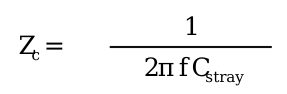
As reactance decreases at higher frequencies, high-frequency radio frequency noise easily bridges the transformer core via capacitive coupling, leaking directly into the component’s internal ground plane where it can cause noise modulation at the Digital-to-Analog Converter stage.
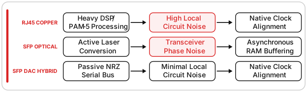
Beyond external noise ingress, traditional RJ45 copper streaming carries a heavy internal computational tax: operating standard 1000Base-T Gigabit Ethernet requires the port’s PHY chip to execute intensive, multi-layered digital signal processing (DSP). The chip must continuously calculate 5-level Pulse Amplitude Modulation (PAM-5), manage active line equalization, and handle real-time echo cancellation. This last task is not about distance: Gigabit Ethernet transmits and receives simultaneously on all four twisted pairs inside the cable, so each transceiver must continuously subtract its own outgoing signal from the incoming one in order to hear the device at the other end. This workload causes the interface chip to draw fluctuating power and generate its own localized high-frequency circuit chatter on the motherboard.
Reference-tier performance within these boundaries therefore demands brute-force physical defenses: permanently disabling Energy Efficient Ethernet (EEE / IEEE 802.3az) in firmware, so the PHY chip never injects transient voltage ripples by cycling through power-saving sleep states, and isolating the circuit boards in dual-layer enclosures—a galvanized steel inner cage nested within a heavy aluminum outer shell, lined with high-permeability electromagnetic absorption sheets that convert airborne radiation into passive thermal dissipation before it can modulate the system clock.
In the language of the core framework’s timing equation, copper’s profile is a trade: J_translation falls to effectively zero—an unbroken electrical path involves no format conversion or clock-recovery hunting—while J_modulated becomes the burden to manage, fed by whatever RFI bridges the transformer and by the PHY’s own processing chatter. The reported psychoacoustic signature follows suit: optimized copper chains are praised for solid, locked-in image focus—the mark of stable native timing—while listeners in electrically noisy homes describe glare or transient hardness, consistent with broadband noise modulating the clock.
Player 2: Audio-Optimized SFP / Optical (Fiber)
Where copper achieves excellence by defensively armoring a native timing loop, optical fiber takes the opposite approach: sacrificing a unified timing system to achieve total galvanic separation from the household grid. By substituting a non-conductive dielectric medium—optical glass—for conductive metal wire, this strategy permanently decouples the audio system from external electrical pollution.
In our Net Algebraic Noise Equation, the fiber optic medium alters the math fundamentally. Because photons cannot transmit electrical current, the attenuation coefficient (A_medium) of a glass line against common-mode noise approaches absolute attenuation: A_medium → −∞ dB.
Whether the upstream network is flooded with high-frequency hash from a high-power desktop computer, a series of smart appliances, or a noisy switching power supply, the interference encounters an absolute barrier. It cannot leap across the optical gap.
Implementation matters, though. Standard commercial networks frequently use Multi-Mode Fiber (MMF), whose wider core—typically 50 to 62.5 microns, roughly one-half to three-quarters the thickness of a human hair—allows inexpensive, less focused light sources. That wide core lets light rays travel along multiple reflective angles, triggering modal dispersion: a temporal blurring that deforms the pulse shape over distance. Distance, however, is the operative word: at Gigabit speeds, modal dispersion is negligible over a two-meter patch cable and remains comfortably within specification even on a roughly 90-meter (300-foot) run to a detached listening room—1000Base-SX multi-mode links are rated for 220 to 550 meters depending on fiber grade. The penalty becomes decisive only at kilometer scale.
1G Single-Mode Fiber (SMF): An optimized audio configuration instead mandates Single-Mode Fiber. Its microscopic 9-micron core—roughly a tenth the width of a human hair—constrains light to a single, linear path, completely eliminating modal dispersion. At domestic distances this is margin rather than necessity; the practical case for Single-Mode is uniformity and headroom—one fiber grade that behaves identically at two meters or two kilometers. Notably, the inter-building scenario is where fiber earns its keep regardless of dispersion: a detached outbuilding typically sits on its own ground rod and power feed, and a non-conductive glass line is the standard defense against the ground-potential differences and lightning-surge paths that a buried copper run would conduct directly into the listening room.
The trade-off for this absolute isolation is the inescapable “transceiver tax” introduced at the chassis boundary. Optical networking demands active electrical-to-optical and optical-to-electrical conversions. When the optical signal hits the Small Form-factor Pluggable (SFP) module on the receiving switch or streamer, a local photodiode must reconstruct the optical pulses as an electrical serial bitstream, which the host’s physical layer (PHY) circuitry then deserializes.
This active conversion process introduces a localized noise floor (N_local). Even when driven by an independent linear sub-rail, the laser drivers and high-speed serialization transistors demand rapid, dynamic current steps from their power supplies. These power draws create localized high-frequency voltage ripples across the module’s ground plane, generating a predictable signature of broadband electrical circuit noise right at the entrance of the chassis.
This format conversion drives up the translation jitter vector (J_translation). Standard 1-Gigabit SFP modules are free-running converters with no clock-recovery circuitry of their own—that timing work happens just downstream, in the host. (Faster enterprise-grade modules sometimes build this circuitry into the module itself, but the 1G modules used in audio systems do not.) Because the link carries no dedicated clock line, the host’s SERDES must perform Clock and Data Recovery (CDR), extracting timing directly from the incoming transition edges: its Phase-Locked Loop (PLL) continuously monitors the stream and micro-adjusts its own oscillator to track phase shifts. This constant “hunting” generates phase noise and packet-arrival jitter that the downstream design must isolate before it can reach the timing rails of the Digital-to-Analog Converter.
The optical camp overcomes these timing liabilities through targeted downstream architecture. Because an optical port replaces the DSP-heavy 1000Base-T copper PHY with a far simpler serial interface, the network silicon sheds its continuous equalization and echo-cancellation workload, dropping into a stable, quiet state of computational execution. (This relief occurs in the interface chip itself—the host CPU’s packet-processing and interrupt load is essentially unchanged by the choice of physical medium.)
To resolve that remaining translation jitter, incoming data is dumped into an asynchronous FIFO (First-In, First-Out) memory buffer. The unstable timing of the upstream transceiver is discarded at this memory boundary; the audio processor then clocks the bits back out using the system’s local, ultra-precise master oscillator.
By separating the physical electricity of the outside world from the local timing domain, the optimized optical path provides a unique combination of infinite environmental isolation and computational stability, assuming the downstream component is engineered to handle the localized noise of the transceiver itself.
Mapped onto the timing equation, fiber inverts copper’s profile: J_modulated is starved of its upstream driver—with A_medium approaching total attenuation, external noise contributes almost nothing—while J_translation becomes the dominant vector, sustained by CDR hunting and only as well-contained as the FIFO stage that follows it. Listener reports mirror the inversion: optical chains are commonly credited with a “black background” where low-level detail emerges from silence, with criticism—typically a slight softening of transient edges—aimed at translation jitter surviving an under-engineered buffer.
Player 3: The Low-Overhead Hybrid (SFP DAC Twinax)
The final architecture challenges the very division between the copper and optical camps. The Small Form-factor Pluggable Direct Attach Copper (SFP DAC) cable is a true hybrid: the standardized enterprise SFP housing, with the active fiber-optic transceiver and glass core replaced by a passive, shielded twinaxial copper conductor. It aims for a unique engineering sweet spot—capturing the native timing symmetry of copper while exploiting the low-overhead processing environment of the SFP subsystem.
The hybrid’s effect shows up in the localized noise variable (N_local) of our Net Algebraic Noise Equation. As the Player 1 copper analysis established, traditional RJ45 streaming requires the local PHY chip to run intensive digital signal processing—5-level Pulse Amplitude Modulation (PAM-5), continuous line equalization, and echo cancellation.
An SFP DAC cable bypasses this entire computational stack. Because a DAC interconnect is a fixed, short-run, point-to-point hardware link—passive versions typically top out around five to seven meters—the network interface card recognizes the connection as a direct serial bus. It drops the complex PAM-5 encoding entirely and transmits data using basic, low-power Non-Return-to-Zero (NRZ) signaling.
Without the need to calculate real-time equalization algorithms, the local PHY chip drops into a near-passive state of computational silence. The processing current steps flatten out, and the self-generated circuit hash on the component’s motherboard drops significantly.
In our timing equation, the SFP DAC cable substantially lowers the translation jitter vector (J_translation) relative to optical fiber, though it cannot drive it to zero. Like any serial SFP link, the twinax path carries no dedicated clock line, so the host’s SERDES must still recover timing from the incoming transition edges. What the DAC cable eliminates is the optical conversion stage itself: no photodiodes, laser drivers, or transceiver electronics add their own phase noise ahead of that recovery loop. The result is a shorter, electrically simpler translation chain between the wire and the network card’s reference clock.
The engineering vulnerability of the SFP DAC cable is its absolute lack of galvanic isolation. As a continuous piece of twinaxial copper, it ties the chassis ground of the upstream network switch directly to the downstream streaming component—any low-frequency leakage or ground-loop current from a standard switching power supply rides the cable straight into the audio component.
However, against high-frequency airborne interference (RFI and EMI), the SFP DAC architecture provides an exceptionally robust defense. Traditional RJ45 cables are vulnerable at their flexible jackets and plastic clip terminations, where shielding gaps can allow airborne radio frequencies to leak onto the signal lines.
In contrast, a premium DAC cable utilizes a heavy, dual-layer foil and braided shield that is mechanically crimped and soldered directly to the solid zinc-alloy metal housings of the SFP connectors. When plugged into the component’s SFP cage, this assembly creates an unbroken, 360-degree Faraday cage around the entire signal path. This structural armor yields an exceptional high-frequency attenuation coefficient (A_medium approx. -70 dB against airborne hash), leaving the architecture vulnerable only to direct, shared DC ground noise.
Companies like Taiko Audio have made this hybrid approach foundational, using dedicated SFP DAC links to offload network interface processing noise away from the server’s main CPU rails—betting that the elimination of localized processing hash outweighs the risk of a shared ground link.
On the timing side, the hybrid keeps both vectors low but not zero: J_translation is trimmed to the short SERDES recovery chain, and J_modulated benefits from the near-silent processing environment—unless a shared-ground path is active, in which case conducted low-frequency noise becomes the modulating force. Reports track this profile: DAC-linked systems are described as pairing copper-like image solidity with much of fiber’s quiet backdrop, with complaints of blurred low-end definition surfacing in setups where upstream grounding is poor.
Architectural Synthesis: The Nonpartisan Matrix
No individual topology holds a permanent monopoly on performance. Each architecture represents a distinct, internally consistent approach to balancing the competing forces of electromagnetic interference, computational loading, and timing precision.
The Three-Way Algebraic Noise & Jitter Summary
To make the core framework’s mathematical baseline concrete, we assign representative engineering estimates—illustrative values, not laboratory measurements—and model the net structural noise (N_net) for each architecture under our normalized 0 dB household baseline. (A note on units: multiplying by the linear coefficient A_medium is equivalent to subtracting its attenuation in decibels from the upstream noise figure, which is how the reductions below are computed; the localized term N_local is tracked separately, because noise powers expressed in decibels cannot be combined by simple arithmetic.)




Passively Isolated Copper (RJ45): High-frequency isolation is limited by the transformer’s stray capacitance. Even with 45 dB of passive rejection, the local motherboard environment must still contend with the significant electrical chatter generated by the PHY chip executing real-time line equalization and PAM-5 decoding.
Audio-Optimized Fiber (1G SMF): The non-conductive glass line achieves an exceptional 90 dB of structural isolation, effectively reducing upstream leakage to zero. However, the system’s total noise floor is hard-capped at -60 dB by the electrical tax of the active SFP transceiver modules, which inject broadband hash directly into the local power rails.
SFP Direct Attach Copper (DAC): The continuous shielding braid, bonded to the zinc-alloy connector housings, yields a massive 70 dB rejection vector against airborne RFI. Because it uses ultra-low-overhead NRZ signaling, local processing noise drops to near-zero. This makes it the quietest electrical environment of the three, balanced against the risk of an un-attenuated, direct path for low-frequency DC ground loops.
The jitter side of the framework completes the circle, using the same illustrative convention. We hold J_intrinsic at 0.3 ps RMS—the integrated jitter of a premium TCXO/OCXO—and derive each J_modulated directly from the topology’s N_net result above, since the core framework defines the modulation term as proportional to net noise amplitude. Totals combine as root-sum-of-squares:




Passively Isolated Copper (RJ45): With no format conversion in the path, the translation term drops out entirely. Copper’s timing risk is concentrated in the 3.6 ps J_modulated term, fed by residual RFI bridging the transformer and by the PHY’s own DSP chatter—so its jitter performance tracks its noise performance: quiet the electrical environment and the clock stays clean.
Audio-Optimized Fiber (1G SMF): The optical gap starves J_modulated of its upstream driver—the 0.6 ps remainder is fed by the transceiver’s own local hash, which dominates fiber’s N_net—but the conversion stage makes J_translation the dominant vector at 3.0 ps. Free-running transceiver clocks and CDR “hunting” inject phase noise that only downstream FIFO buffering can discard.
SFP Direct Attach Copper (DAC): The hybrid runs both variable terms low. Eliminating optical conversion trims J_translation to 1.0 ps across the short SERDES recovery chain, and the near-silent processing environment holds J_modulated to just 0.2 ps—provided the shared DC ground path stays clean, since conducted noise would re-feed the modulation term.
The remaining term, J_intrinsic—the native purity of the master oscillator itself—is independent of the medium entirely, which is why the clocking hierarchy is treated separately in the closing section.
| Engineering Vector | Passively Isolated Copper (RJ45) | Audio-Optimized Fiber (1G SMF) | SFP Direct Attach Copper (DAC) |
|---|---|---|---|
| Primary Noise Strategy | Multi-stage passive shielding and magnetic isolation transformers. | Absolute galvanic isolation via non-conductive dielectric glass lines. | Complete 360-degree Faraday cage bonded to zinc-alloy connector housings. |
| PHY Computational Loading | High. Heavy DSP overhead required for continuous PAM-5 line equalization. | Low. Bypasses heavy copper processing arrays using serial NRZ signaling. | Microscopic. Ultra-short point-to-point link drops DSP overhead entirely. |
| Master Clock Alignment | Runs directly on native 25 MHz controllers; no optical conversion stages in the timing path. | Free-running transceiver clocks require downstream asynchronous FIFO RAM buffering. | Electrical-domain serial link; host SERDES clock recovery remains, minus any transceiver-added phase noise. |
| Primary System Sensitivity | Highly vulnerable to upstream power supply noise and environmental RFI/EMI leakage. | Highly dependent on the local power rail regulation feeding the active SFP module. | Vulnerable to direct, shared DC ground loops between connected components. |
| What Do We Hear | Solid, locked-in imaging; potential glare or hardness in electrically noisy environments. | “Black background” and low-level detail; softened transients when buffering is under-engineered. | Copper-like solidity with a quiet backdrop; a slight blur in low-end definition if ground loops are present. |
| Evolutionary Runway | Highly mature; future improvements focus on incremental material science refinements. | Emerging runway; leaves significant room for custom, low-phase-noise transceivers. | Emerging hybrid path; optimized via boutique pin-isolation and advanced metallurgy. |
The Frontier of Future Innovation
The relative maturity of these interfaces shows where the high-end audio industry is headed. Traditional copper RJ45, refined over decades of enterprise and consumer application, is a mature, thoroughly mapped engineering school whose future is largely evolutionary—a game of millimeters, squeezing final fractions of a decibel of isolation from advanced composite shielding materials.
The SFP framework—encompassing both single-mode optical fiber and passive twinaxial DAC cables—is a younger, more dynamic paradigm. Because the consumer market still relies on off-the-shelf enterprise transceivers designed for data volume rather than low-phase-noise analog rendering, this ecosystem has a long runway for breakthroughs.
The next frontier is custom, audio-specific SFP modules built from the ground up to preserve phase integrity. As boutique manufacturers integrate low-noise linear sub-regulation, discrete clock trees, and silicon photonics directly into the SFP form factor, the traditional “transceiver tax” will continue to drop.
Where to Begin: Prioritizing the Chain from Modem to DAC
A practical question follows from all of this. Noise and timing error are injected all along the path—from the ISP modem, through routers and switches, to the streamer—so where does optimization deliver the most bang for your buck, as they say? The chain is long, and it is tempting to treat every link as equally worthy of attention and budget. It is not.
Two things make the last hop dominant. First, proximity: the bits arrive intact wherever they have been, but the high-frequency noise and timing error riding alongside them matter only in proportion to where they enter the sensitive analog and clock circuitry—and the final network link—from the switch to the streamer—lands directly in the domain that feeds the DAC, while upstream noise is attenuated by every hop before it arrives. Second, workload: recovering a marginal or noisy signal forces the streamer’s interface chip and processor to work harder—more equalization, error handling, and buffering—and that work is itself a noise source inside the chassis, right beside the circuitry that reconstructs the signal. A cleaner signal lets the streamer do less of it and hold its noise floor lower.
The order of operations follows: work backward from the DAC. The changes that buy the most improvement are the ones closest to the streamer—the last switch that feeds it, the cable running from that switch to the streamer, and any isolation device at that connection. A clean break there does two jobs at once: it stops noise arriving from upstream and lightens the streamer’s workload. From there the gains diminish with distance but never quite vanish: each cleaner link back toward the modem shaves a little more from the burden the streamer must reconcile. Secure the last hop first, then keep working upstream, all the way to the modem, for the smaller improvements that remain.
One qualification keeps this from being absolute. Common-mode and ground-borne leakage do not respect the hop-by-hop model; they can couple across links so that even a distant switching supply makes itself heard. The remedy is the same—a single galvanic or optical break near the streamer interrupts that path as well as any local one—so even the exception points back to the same rule: a well-placed break close to the DAC does most of the work, wherever the noise begins.
Additional Consideration: The Clocking Hierarchy
One additional layer of hardware optimization remains: the master timing hierarchy. Whatever the transmission medium, the physical layer circuitry requires a rigid time base to modulate and interpret the serial lines—in Gigabit Ethernet architectures, a reference clock locked at 25 MHz.
Designers of reference-tier networking components face a pivotal crossroads that dictates how net noise interacts with the timing engine: an external 10 MHz master reference clock, or a native 25 MHz oscillator. It is a classic trade-off between baseline crystal purity and direct circuit simplicity.
A clarification is warranted here, because the word clock carries a specific connotation in high-resolution audio. When audiophiles speak of a clock, they almost always mean the DAC’s own master clock, where 10 MHz has become the de facto standard—internal or external. The clock under discussion in this section is a different animal—the reference that times the Ethernet physical layer, whose native requirement is 25 MHz, not 10 MHz—and the two should not be conflated. The network reference never directly times the conversion of samples into analog; that remains the exclusive province of the DAC’s own master clock. Its influence on what you ultimately hear is the indirect one this paper has traced throughout—noise and phase disturbance coupling across the interface—rather than any direct sharing of the audio time base.
To understand how these choices alter the noise behavior across the system, we can observe the Net Noise and phase flow pathways of each implementation:
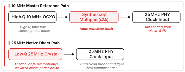
The argument for the 10 MHz master clock paradigm—ubiquitous in laboratory instrumentation and top-tier digital playback frameworks—is rooted in the physics of quartz crystal manufacturing. Slicing a quartz blank to resonate naturally at 10 MHz allows for a relatively thick, mechanically stable crystal geometry, typically cut using specialized SC-cut configurations and housed within a temperature-controlled oven (OCXO). This physical mass yields an exceptionally high mechanical Quality Factor (Q factor).
A high-Q oscillator acts like a massive mechanical flywheel, demonstrating near-perfect thermal stability and absolute resistance to physical vibrations. Consequently, a premium 10 MHz source achieves incredibly low close-in phase noise—the timing variations that occur immediately adjacent to the center frequency, from 1 Hz to 100 Hz offset.
The penalty for this structural purity is mandatory frequency translation. An Ethernet physical layer chip cannot interpret a 10 MHz signal directly, so the incoming reference must be multiplied up to the required 25 MHz by an internal Phase-Locked Loop (PLL) or frequency synthesizer—a multiplication factor of N = 2.5.
According to the laws of RF physics, frequency multiplication degrades phase noise sidebands across the board according to the equation:
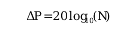
For a multiplication factor of 2.5, this imposes a mathematically inescapable penalty:

The pristine timing signature of the 10 MHz crystal is instantly degraded by roughly 8 dB. Furthermore, the active multiplier microchip introduces its own residual additive jitter and a flat broadband noise floor generated by its internal switching transistors.
To bypass this penalty and the complexity of an internal PLL, designers can opt for a native 25 MHz hierarchy: the oscillator drives the network physical layer chip directly, eliminating the synthesizer entirely. Direct drive keeps the broadband phase noise floor exceptionally flat, preventing high-frequency electronic glare from infiltrating adjacent components.
The limitation of the native 25 MHz approach returns to crystal geometry: to vibrate naturally at more than double the speed of a 10 MHz crystal, the quartz blank must be sliced significantly thinner, and its mechanical Q factor plummets.
A low-Q oscillator behaves like a lightweight pendulum rather than a heavy flywheel—highly susceptible to thermal drift, power-rail fluctuations, and chassis-borne microphonic vibrations—so native 25 MHz crystals show a notable increase in close-in phase noise.
Psychoacoustically, these two signatures are reported to impact a high-resolution system in characteristic ways at the final conversion stage. Close-in phase noise behaves as low-frequency timing modulation, tending to obscure low-level environmental cues, soundstage depth, and low-frequency pitch definition; an elevated broadband noise floor instead adds a fine high-frequency texturing that can manifest as an unnatural sheen or transient hardness in the upper-midrange.
Ultimately, neither clocking hierarchy holds a structural monopoly. A native 25 MHz topology wins on pure simplicity, keeping broadband circuit noise to a minimum. An external 10 MHz reference accepts the mathematical penalty of an internal multiplier, betting that ultra-low-noise discrete distribution and independent linear regulation can hold additive jitter below the threshold of measurement—capturing the deep soundstage focus of a high-Q master oscillator.
Trending Articles
See all
High End Vienna 2026: Loudspeakers Under $50k
- Jun 17, 2026
Dynaudio Sub 6 Powered Subwoofer Review
- Dec 02, 2025




By Jason Methfessel
I've gotten my toes wet in Hi-Fi Audio while working in the backend on databases and website development for Nextscreen, LLC - Publisher of The Absolute Sound. Only recently have I begun my journey to the foreground to help the editorial staff produce content for our digital offering, which include theabsolutesound.com, YouTube, Substack, and our twice weekly newsletter. My primary focus will be to review lower-cost, entry-level equipment for our subscribers. In my free time in enjoy riding my bicycle and have recently picked up downhill skiing.
More articles from this editor

Read Next From Blog
See all
Removing Ethernet Noise
- Jul 01, 2026
JL Audio Unveils Advanced New Full-Range Loudspeaker
- Jun 10, 2026

